Changes are often not pretty.
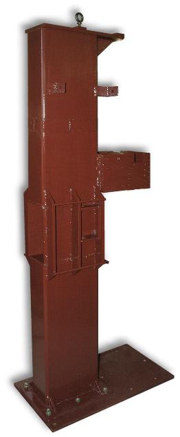
When we found that we needed to add 3" to the frame height it was one of those "oh dang" sinking stomach feelings.
On the incomplete frame it was fairly easy to add to the top then weld on the top flange.
But on the finished X1-a frame the problem was the top flange and gussets were already welded on as well as the motor brackets tacked on.
More below. . .
We also had two problems with the original height adjustment.
Somewhere I missed a dimension and the adjustment was not sufficient.
There was also a possibility of interference at the top of the adjustment.
A motion layout showed the end of the threaded rod would come very close to striking the springs.
These changes could have been avoided if I had taken time to make more than a hand sketch of the whole when we started construction.
The errors did not prevent the hammer from running.
We tested and demonstrated it prior to the changes.
However, the adjustment range was not what we expected so we made these changes.
Lengthening the Frame
|
This is a change you do not want to have to make.
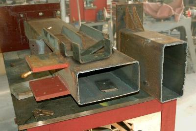
To raise the frame we needed a short section of structural.
However, we had no left over material, neither did the warehouse and purchasing just a few inches of material was out of the question.
So, we made bent sections of bar with the same radius as the structural tube.
Four pieces for each frame were bent on the hydraulic press then sawed to match the frame structural.
On the incomplete X1b modifying the frame was easy since the top flange and gussets had not been welded on.
The spacers were added to the top and it was a clean job.
On the X1a we had to cut the frame in two near the middle of the top section.
We tried to have the frame sawed on a large saw but its shape kept it from fitting. So we had to torch it in two.
|
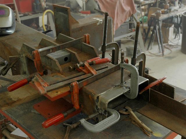
Splicing straight sections with obstructions is always tricky especially when hand torch cut and ground.
This is another case where you cannot have enough clamps.
The finished splice is not pretty and will always stand out as a mistake.
Height Adjustment Change
This was not a difficult change to make but required making new toggle link blocks and the purchase of expensive left hand Acme rod and nuts.
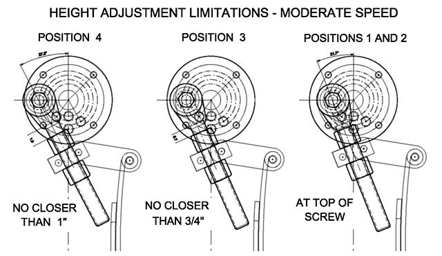
This change was made for two reasons.
There was probable interference at the end of the Acme screw as shown above.
This layout does not show the toggle arms with more than the static angle which produces actual interference.
This was something I should have checked before construction.
But the hammer ran fine with the adjustment at the bottom which let us do our initial testing.
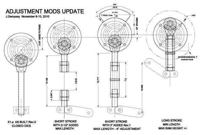
After having missed the interference problem and the stroke height needs with my pencil sketches I made accurate CAD layouts to determine distances.
While making these changes we found we needed more adjustment and added 1/2" spacers under the bearings to raise the shaft some more.
Our 2-1/2" frame extension should have been 3-1/2".
After going to all the trouble to use left and right hand threads I realized we could use a single long tubular "nut" and a long right hand thread.
This is the system we will use on the X2.
The other issue was dimensional errors that would not let the die space be adjusted close enough for light work.
To fix these problems required a change in the method of adjustment which also required the change in the frame height.
Other Changes:
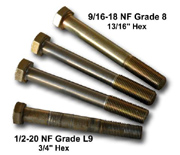
During testing we had trouble with some stripped bolts.
It could have been for a number of reasons or just bad luck.
Special oversized bolts were made and the rams redrilled and taped for the oversized bolts.
The Rams were also drilled and rearmed for a 1" shank tool. This is for future optional tooling we want to test.
See
Detail Touches for more about the special bolts.
These in turn are now being replaced by 5/8"-11 threaded studs with 1/2" ends to fit the rockers.
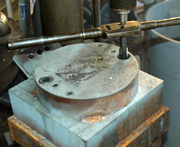
The X1a anvil and anvil cap were drilled with large 3/4-10 countersunk holes.
This was for the special tooling mentioned above.
The anvil cap and die holder can be removed creating 5" plus height for for future/optional tooling.
The anvil cap also has extra 1/2" drilled and tapped holes for various tooling.
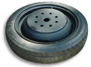
Our wheels originally had 4 bolt holes to fit the 4 bolt pattern on the crank hub.
It was about this time that we started hearing from people who had built heavy tire-hammers that their tires were wearing out, particularly at the short distance where the drive wheel initially engages the tire.
So we laid out a second set of holes so that they could be repositioned 8 times.
Springs: The springs work as-is but are right on the edge of sufficiency.
Future updates and the X2 should have 3 leaf spring bundles instead of 2 with nearly full length secondaries.
More Changes:
The X1 hammers are complete and running so it is doubtful they will see any more major changes.
The most likely possibility of change is to replace the auto wheel assembly for a flat belt drive (more R&D).
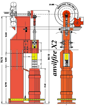
Our X2-110 hammer design is a different story.
We learned a lot building and operating the X1.
The most important lesson was that modifying the tire-hammer drive wheel is a bad design decision.
While our modification was similar to a flat hub wheel it was still a mod that means the wheel is difficult to replace and the tire hard to change.
The current crop of tire hammers with a plate welded to the wheel are not maintainable at all.
The design of our X2 hammer moves the drive wheel to the back like the
Costa Rician Tire Hammer.
This in turn makes it natural to have a jog in the frame.
It is not pretty but keeps the hammer flat on the back and compact.
This design also has significantly longer guides to keep the ram and dies under better control.
Precision forging, even open die requires a tight ram with little wobble.
We have also turned the ram 90 degrees so that the long axis is aligned with the frame pass-through.
This is more useful for long work cross section dies.
The dies being rotated also provide infinite work space across the dies.
This is the same arrangement as the Fairbanks Power Hammer.
The spring mounting has also been improved.
The X1's have two holes drilled in the springs, one at the most critical stress point (looked good on paper - not in reality).
This means the springs WILL break at that point, probably sooner than later.
Logical Design: Make one change and others follow. . .
When the wheel is moved to the back the motor must be put on the opposite side so that the electrical connections are on the outside.
The location of the motor platform also requires that the actuating lever pass through the frame adding a bit of complexity to both parts.
However, this should not be a problem if the plans are followed carefully.
The Plan, The plan . . .
June 7, 2015: Most of the X2 drawing details have been finished for a couple years.
There are a few yet to be completed but most skilled builders could do without. I'll make an effort . . .
Meanwhile we've given away a couple sets in hope that someone else will build the hammer so we would have some input and perhaps even photos of the build.
Why am I not building the X2?
Time, Money AND I have an X1 already. . . .
Besides which my next builds will be a small 30-40 pound hammer and I REALLY want to build a 220 pound (100kg) hammer to make some products I'd like to sell.
SO. . . we will see. I've stopped making promises about future projects.
July 22, 2017: Little progress has been made finishing the X2 plans. However, the X1 top spring bolts have both failed on the right hand side.
The X2 design does not use a through bolt and there are TWO bolts holding the spring clamp.
We will be making this modification in the near future to get the hammers running again.
My surprise is that I thought the spring would break at the bolt location, not the bolt fail.
INDETERMANENT DELAY:
Published plans for the X2 Hammer are delayed due to being too complicated or expensive for most builders and due to some unproven parts.
Currently there is no plan to build a test version of the X2 unless someone wants to give us the money to do so as an R&D project. . .
With little chance of recuperating our costs in the plans we have decided not to finish them at this time and work on more pressing projects.
|



We also had two problems with the original height adjustment. Somewhere I missed a dimension and the adjustment was not sufficient. There was also a possibility of interference at the top of the adjustment. A motion layout showed the end of the threaded rod would come very close to striking the springs.
These changes could have been avoided if I had taken time to make more than a hand sketch of the whole when we started construction. The errors did not prevent the hammer from running. We tested and demonstrated it prior to the changes. However, the adjustment range was not what we expected so we made these changes.
Lengthening the Frame
To raise the frame we needed a short section of structural. However, we had no left over material, neither did the warehouse and purchasing just a few inches of material was out of the question. So, we made bent sections of bar with the same radius as the structural tube. Four pieces for each frame were bent on the hydraulic press then sawed to match the frame structural.
On the incomplete X1b modifying the frame was easy since the top flange and gussets had not been welded on. The spacers were added to the top and it was a clean job. On the X1a we had to cut the frame in two near the middle of the top section. We tried to have the frame sawed on a large saw but its shape kept it from fitting. So we had to torch it in two.
Splicing straight sections with obstructions is always tricky especially when hand torch cut and ground. This is another case where you cannot have enough clamps. The finished splice is not pretty and will always stand out as a mistake.
Height Adjustment Change
This was not a difficult change to make but required making new toggle link blocks and the purchase of expensive left hand Acme rod and nuts.After going to all the trouble to use left and right hand threads I realized we could use a single long tubular "nut" and a long right hand thread. This is the system we will use on the X2.
The other issue was dimensional errors that would not let the die space be adjusted close enough for light work. To fix these problems required a change in the method of adjustment which also required the change in the frame height.
Other Changes:
See Detail Touches for more about the special bolts.
These in turn are now being replaced by 5/8"-11 threaded studs with 1/2" ends to fit the rockers.
The X1a anvil and anvil cap were drilled with large 3/4-10 countersunk holes. This was for the special tooling mentioned above. The anvil cap and die holder can be removed creating 5" plus height for for future/optional tooling. The anvil cap also has extra 1/2" drilled and tapped holes for various tooling.
Our wheels originally had 4 bolt holes to fit the 4 bolt pattern on the crank hub. It was about this time that we started hearing from people who had built heavy tire-hammers that their tires were wearing out, particularly at the short distance where the drive wheel initially engages the tire. So we laid out a second set of holes so that they could be repositioned 8 times.
Springs: The springs work as-is but are right on the edge of sufficiency. Future updates and the X2 should have 3 leaf spring bundles instead of 2 with nearly full length secondaries.
More Changes:
The X1 hammers are complete and running so it is doubtful they will see any more major changes. The most likely possibility of change is to replace the auto wheel assembly for a flat belt drive (more R&D).Our X2-110 hammer design is a different story.
We learned a lot building and operating the X1. The most important lesson was that modifying the tire-hammer drive wheel is a bad design decision. While our modification was similar to a flat hub wheel it was still a mod that means the wheel is difficult to replace and the tire hard to change. The current crop of tire hammers with a plate welded to the wheel are not maintainable at all.
The design of our X2 hammer moves the drive wheel to the back like the Costa Rician Tire Hammer. This in turn makes it natural to have a jog in the frame. It is not pretty but keeps the hammer flat on the back and compact.
This design also has significantly longer guides to keep the ram and dies under better control. Precision forging, even open die requires a tight ram with little wobble.
We have also turned the ram 90 degrees so that the long axis is aligned with the frame pass-through. This is more useful for long work cross section dies. The dies being rotated also provide infinite work space across the dies. This is the same arrangement as the Fairbanks Power Hammer.
The spring mounting has also been improved. The X1's have two holes drilled in the springs, one at the most critical stress point (looked good on paper - not in reality). This means the springs WILL break at that point, probably sooner than later.
Logical Design: Make one change and others follow. . .
When the wheel is moved to the back the motor must be put on the opposite side so that the electrical connections are on the outside. The location of the motor platform also requires that the actuating lever pass through the frame adding a bit of complexity to both parts. However, this should not be a problem if the plans are followed carefully.
The Plan, The plan . . .
June 7, 2015: Most of the X2 drawing details have been finished for a couple years. There are a few yet to be completed but most skilled builders could do without. I'll make an effort . . .Meanwhile we've given away a couple sets in hope that someone else will build the hammer so we would have some input and perhaps even photos of the build.
Why am I not building the X2? Time, Money AND I have an X1 already. . . . Besides which my next builds will be a small 30-40 pound hammer and I REALLY want to build a 220 pound (100kg) hammer to make some products I'd like to sell.
SO. . . we will see. I've stopped making promises about future projects.
July 22, 2017: Little progress has been made finishing the X2 plans. However, the X1 top spring bolts have both failed on the right hand side. The X2 design does not use a through bolt and there are TWO bolts holding the spring clamp. We will be making this modification in the near future to get the hammers running again. My surprise is that I thought the spring would break at the bolt location, not the bolt fail.
Published plans for the X2 Hammer are delayed due to being too complicated or expensive for most builders and due to some unproven parts. Currently there is no plan to build a test version of the X2 unless someone wants to give us the money to do so as an R&D project. . . With little chance of recuperating our costs in the plans we have decided not to finish them at this time and work on more pressing projects.