First and foremost I want to point out that I designed these hammers MY way.
It was not the easiest way nor the most economical way to build hammers.
Some elements are the way they are to prove an idea.
These are NOT Junk yard hammers, they are hammers designed to be built by and used by metalworking professionals or highly skilled hobbiests.
Since building them I have done a lot or examination of the design and have changed the plans we (might) publish to reflect these changes.
Chief among the changes is how the drive wheel is mounted.
The X1 and the common tire hammer modifies the drive wheel.
This is a bad idea for several reasons.
One is that it makes tire replacement difficult.
The other is that while it seems to save effort it does not.
Our new design will have the unmodified wheel and tire on the back similar to the Costa Rica Tire Hammer so that it is as easy to replace as any automobile tire.
This in turn requires the motor to be moved from the left to the right for convienient access to the electrical box.
Other changes include correcting design mistakes and making a few improvements.
This project started with a hard push with the goal to have the hammers running for the anvilfire 11th aniversary hammer-in in 2008.
The result was a disaster.
The design was not complete and mistakes were made.
We were trying to make two hammers at once and did not have time for one.
We kept working while the hammer-in was supposed to be going on after a number of near all-night work sessions. . . I was a crispy critter at the end of the weekend.
The project slowed to a creep due to economics, health issues of the participants and scheduling conflicts.
What was supposed to take a month stretched to over 4 years.
This should not reflect on the actual time required to build one of these hammers.
 The most major mistake was not having a throughly checked assembly drawing.
Many of the details were complete but the assembly was a single pencil sketch with multiple starting points for dozens of dimensions determining the height stackup.
The most major mistake was not having a throughly checked assembly drawing.
Many of the details were complete but the assembly was a single pencil sketch with multiple starting points for dozens of dimensions determining the height stackup.
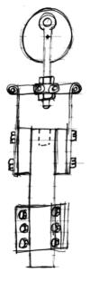
The mechanical arrangement for this hammer started as an idea for a rubber-band hammer.
This design has rubber bands or nylon straps stretched between two arms and the pitman raising the ram by the middle of the band.
While this sounds bizarr it is a reversal of how a number of hammers were built including the Bradley "strap" hammers.
From this idea the sketch at left was made using leaf springs instead of rigid arms and toggle links instead of rubber bands.
The machinery needed to build these hammers is modest but not in the range of all.
While a Junk Yard Hammer may be built using the cheapest easiset methods, often arc welding everything together, this is NOT a Junk Yard hammer.
It is a shop built hammer designed to be maintainable and have a long life.
It can be dissasembled for moving, adjustments made and dies replaced.
X1 Specifications
- 110 Pound (50 kg) Ram
- 1010 Pound Anvil and Base 9.2 : 1 Ratio
- 2 HP 1PH 1800 RPM Motor
- 290 Blows Per Minute Max.
- 4 Working Strokes 2.5, 3.2, 3.8, 4.5"
- 0 to 3" Open Space
- 0 to 6" Working Height
- 3 x 5" (1.75 x 5" STD.) Dies
- 6" x 12" Frame Pass Through
- 24" Wide, 33" Deep, 92" Tall
|
OPTIONS
The X1 was calculated to need slightly less than 1HP (.746kW) to operate and thus was speced with a 1.5HP motor.
However, the commonly available 1.5HP motors have a light frame with a 5/8" diameter shaft which was deemed too light for this application.
Substitute 1.5HP motors were more expensive so the 2HP (1.48kW) NEMA G145T Farm motors with 7/8" shafts were used.
Big BLU die holders and dies were used on the X1.
Similar sized bolt on dies could be substituted and will be an option on the published X2 plans.
|
|
While this hammer uses the DuPont style toggle to great advantage, the spring arrangement is unique.
Its primary advantage is efficient use of mass.
It does not have the heavy arms and links of other mechanical hammers and the springs are part of the ram.
This converts what is dead ineffient reciprocating weight on other hammers into working mass.
IF you use this arrangement PLEASE give the inventor (Jock Dempsey AKA the anvilfire guru) credit.
We put these ideas out there freely but they cost a lot of time and effort.
|
|
The key to this design is the spring adjustment rockers.
These were the first parts detailed and the first parts made.
Both the rockers and rocker caps were made using a large drill press and a small 4" x 6" cut off saw.
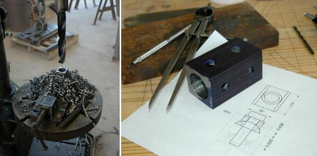
Typical of many machined parts more material is reduced to chips than that in the remaining part.
Above we are making 8 rockers caps, 4 for each hammer.
The 1.5" hole was drilled on a 25" Champion drill press but could have been bored on a small lathe or milling machine.
After drilling, the parts were sawed out.
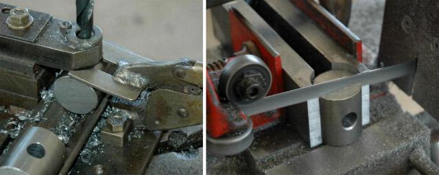
The rockers are made by cross drilling lengths of round bar then sawing them off.
The drilling fixture in use was made for another job.
It was not necessary, just handy.
The fixture holding the parts for sawing was drilled with the same 1.5" drill as the rocker caps.
For building one machine a wooden V clamp would work.
This same round stock is also used for the main shaft.
The final step on the rockers was to egg out the holes with a die grinder for the change of angle during adjustment.
This task could have also been done on a milling machine but the die grinder was very efficient for this task.
Links


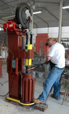
Since building them I have done a lot or examination of the design and have changed the plans we (might) publish to reflect these changes. Chief among the changes is how the drive wheel is mounted. The X1 and the common tire hammer modifies the drive wheel. This is a bad idea for several reasons. One is that it makes tire replacement difficult. The other is that while it seems to save effort it does not. Our new design will have the unmodified wheel and tire on the back similar to the Costa Rica Tire Hammer so that it is as easy to replace as any automobile tire. This in turn requires the motor to be moved from the left to the right for convienient access to the electrical box. Other changes include correcting design mistakes and making a few improvements.
This project started with a hard push with the goal to have the hammers running for the anvilfire 11th aniversary hammer-in in 2008. The result was a disaster. The design was not complete and mistakes were made. We were trying to make two hammers at once and did not have time for one. We kept working while the hammer-in was supposed to be going on after a number of near all-night work sessions. . . I was a crispy critter at the end of the weekend.
The project slowed to a creep due to economics, health issues of the participants and scheduling conflicts. What was supposed to take a month stretched to over 4 years. This should not reflect on the actual time required to build one of these hammers.
The mechanical arrangement for this hammer started as an idea for a rubber-band hammer. This design has rubber bands or nylon straps stretched between two arms and the pitman raising the ram by the middle of the band. While this sounds bizarr it is a reversal of how a number of hammers were built including the Bradley "strap" hammers. From this idea the sketch at left was made using leaf springs instead of rigid arms and toggle links instead of rubber bands.
The machinery needed to build these hammers is modest but not in the range of all. While a Junk Yard Hammer may be built using the cheapest easiset methods, often arc welding everything together, this is NOT a Junk Yard hammer. It is a shop built hammer designed to be maintainable and have a long life. It can be dissasembled for moving, adjustments made and dies replaced.
X1 Specifications
The X1 was calculated to need slightly less than 1HP (.746kW) to operate and thus was speced with a 1.5HP motor. However, the commonly available 1.5HP motors have a light frame with a 5/8" diameter shaft which was deemed too light for this application. Substitute 1.5HP motors were more expensive so the 2HP (1.48kW) NEMA G145T Farm motors with 7/8" shafts were used.
Big BLU die holders and dies were used on the X1. Similar sized bolt on dies could be substituted and will be an option on the published X2 plans.
A UNIQUE MECHANICAL ARRANGEMENT : DEMPSEY QUARTER ELLIPTIC
While this hammer uses the DuPont style toggle to great advantage, the spring arrangement is unique. Its primary advantage is efficient use of mass. It does not have the heavy arms and links of other mechanical hammers and the springs are part of the ram. This converts what is dead ineffient reciprocating weight on other hammers into working mass.IF you use this arrangement PLEASE give the inventor (Jock Dempsey AKA the anvilfire guru) credit. We put these ideas out there freely but they cost a lot of time and effort.
The key to this design is the spring adjustment rockers. These were the first parts detailed and the first parts made. Both the rockers and rocker caps were made using a large drill press and a small 4" x 6" cut off saw.

Typical of many machined parts more material is reduced to chips than that in the remaining part. Above we are making 8 rockers caps, 4 for each hammer. The 1.5" hole was drilled on a 25" Champion drill press but could have been bored on a small lathe or milling machine. After drilling, the parts were sawed out.
The rockers are made by cross drilling lengths of round bar then sawing them off. The drilling fixture in use was made for another job. It was not necessary, just handy. The fixture holding the parts for sawing was drilled with the same 1.5" drill as the rocker caps. For building one machine a wooden V clamp would work. This same round stock is also used for the main shaft.The final step on the rockers was to egg out the holes with a die grinder for the change of angle during adjustment. This task could have also been done on a milling machine but the die grinder was very efficient for this task.
Links