Background:
I am a 17 year old who lives in Mississauga, Canada.
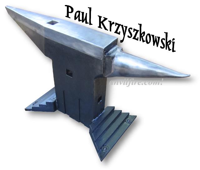
The anvil was a high school metal shop project.
I was asked my teacher what I would like to do for the semester, I presented him with the idea of a anvil.
 Planning:
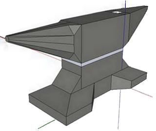
I knew I wanted a double horn anvil. I already have
a few London Patterns so making
another one would be of no benefit to me.
I was asked to present a few drawings to my
teacher.
To the right is one of the designs I came up with
on Google Sketchup.
Originally I planned on making the anvil out of forklift tines, but my ideas changed once I found some of the material which was available at school.
I was shown a few pieces of 3.5" x 1.5" mild steel, so my design changed to accommodate the new material.
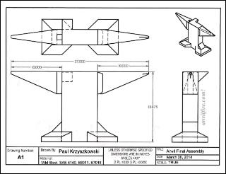
After much research (much of it done on anvilfire.com) I came up with the following drawing.
(Left) A final assembly drawing done in Solid Edge Acedemic
Formal drawings (as shown) are part of the process in a metalworking class.
So we have the design or assembly drawing and details.
Often at least one revised drawing is required as well as a bill of materials.
We cleaned up all of Paul's CAD drawings provided and reworked the title block.
The full size set of four drawings and a marked up version of the assembly drawing can be found in this Adobe PDF
Paul-K-Anvil.PDF.
-guru
 Features of Design:
I designed the anvil with several features
- Square tapered horn because it offers far more utility than the horn of a London pattern anvil
-Third Horn (after some thought and discussion I decided against it)
-The height of this anvil is 13 7/8'' tall, this is 50% taller than a London pattern anvil of similar weight.
The reasoning for the height was the material was available, and it would provide more mass under the hammer making forging more efficient.
- 1/2'' Holes drilled in feet to make it easy to mount to any stand
I made changes to the design while making the anvil.
First was to make a stepped horn instead of a horn which is level to the rest of the face as originally drawn.
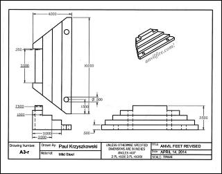
Second was to make stepped feet as are often seen in Austrian anvils. (drawing at left)
Third, I added 1" handling holes, as well as a 1" square hole through the body of the anvil.
I thought as long as I had access to a milling machine I should use it. The square hole in the body of the anvil is a common feature in chainmaker's anvils.
I did not see any disadvantage in adding it to my anvil.
The cross hole (like a Chain Maker's anvil) should be rectangular or large enough for a 1" square bar PLUS wedges.
The hole was used to support a variety of tools including bottom swages, hinged top swages and small "Tommy" or treadle hammers. A 1" hole can only support a 3/4" bar PLUS wedges. This is a little springy except for light applications. -guru
 Fabrication:
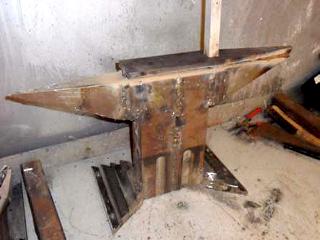
All the needed pieces where cut on the bandsaw, milled, ground, and welded together.
It can be seen in the photo how all the individual pieces looked.
The body consisted of 4 main parts, each horn was made of two parts, and the stepped feet where made of 3 parts each.
Each piece had a v groove ground to at least 3/4".
The body was welded together using 1/8" 7018 electrodes.
I would have liked to use 6011 for a root pass but I did not have any on hand.
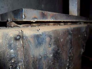
The top plate was made from 3'' x 1/2'' x 18'' 4140
flat bar. The plate first cut to fit the
top of the anvil. Once the plate fit, a spacer of
3/8'' bar was placed along the centre of
the face, and around the hardy hole. the remaining
3/8'' gap was welded with 7018 rods.
The plate was not preheated before welding. Being
as thin as it was it heated up after a
few passes.
Two photos above show the process
If I were to do it again I would have ground the
face of the anvil to a deep V-Groove and
abandoned the 3/8'' rod altogether. Welding in that
gap proved very challenging for me,
it was difficult to remove the slag.
Once the anvil was welded I ground all of the welds down.
The last step in the shaping was to grind the horn round.
I used a 7" grinder which made short work of the mass.
I hammered the tip of the horn upwards, which is why it looks the way it does.
NOTE: In Paul's video he mentions the need to chamfer the hardy hole after hardening.
It is much better to put a healthy radius on the face and hardy hole before hardening the anvil.
It is much easier on the files and to do as well as removing edges that can burn during heat treating.-guru
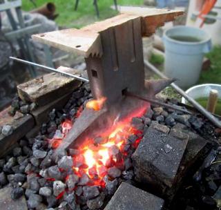 Heat Treating:
The anvil was heat treated in my coke forge. I
brought it up to temp, and with my father
we poured water on the face.
Loss of heat on the horn could have been prevented by covering it with a Kaowool blanket while in the forge to assure a more thorough heat.
The water was in five 40 gallon garbage bins plus about 20 gallons in a wheelbarrow and was just barely enough for this size anvil and a partial heat.
While the anvil was manageable with two people the operation could have used more helpers.
A jib crane can make handling the anvil smoother.
-guru
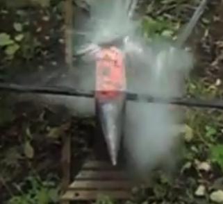
When we ran low on water, we flipped the anvil upside down in a wheelbarrow filled with water.
This is so the residual heat would not travel up the face and temper the anvil.
No tempering was done.
4140 in such a thick cross section does not need tempering.
The hardening was successful.
The face does not easily dent under a hammer, but is softer compared to my 80lb Peter Wright (Which is extremely hard)
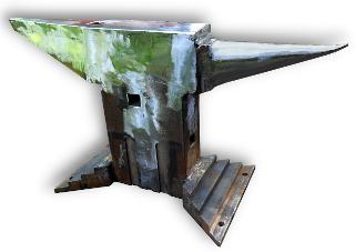
 Finishing:
Once the heat treating was complete It was time to
finish the anvil. I wire wheeled
everything, polished the face, and painted the
rest.
DONE!
The project took about 5 months to complete, 75 to 100 hours, and $100 from my pocket (Electrodes, 4140, coke, grinding wheels).
Postmortem
When done with the project Paul says he would never do it again.
But I see on YouTube that he has made other smaller anvils.
It gets in your blood. . .
He says for the cost and time that he should have built a power hammer.
Videos:
I made 3 videos while I was completing the anvil.
They can be found on Youtube.
Making the Anvil - Layout, Cutting, Machining,
Grinding, Welding
http://youtu.be/Hzkt2bGN3oo
Heat Treating the Anvil
https://www.youtube.com/watch?v=akcF62mJvmQ
Finishing the Anvil
https://www.youtube.com/watch?v=xAXODvcPvJs
October 4, 2014
Guru's Comments:

Faux Markup
The drawing above is a faux marked up print similar to what you would actually find in many shops during such a project.
As built drawings are filed and used to produce the next generation of drawings and details if the same item is to be made again.
On complex engineering drawing prints you will often find markups, calculations, coffee stains and/or cigarette burns. . .
all indicative of long hours of study, rethinking and pondering options.
We cleaned up all of Paul's CAD drawings and reworked the title block.
The full size set of four drawings and a cleaner version of the marked up drawing can be found in this Adobe PDF
Paul-K-Anvil.PDF.
SCALE: We marked the drawings as "TRUE" scale as they are proportionally correct.
In CAD drawings there is no such thing as scale except internal to the drawing due to output varying in size.
This is our second young Canadian to submit a high quality shop made anvil project.
In this case it is a high school senior metalworking class project so it included formal CAD drawings based largely on research using this web site.
The project progressed as many do, changes were made based on material availability and the project development.
Available machinery was taken advantage of, a reason I suggest to many that they take trade school or adult classes.
Tuition is a fraction of the cost of having someone else do the work of having access to the machinery and facilities.
In this case a large heavy duty band saw was used to cut the stock and a milling machine to square stock and make grooves for handling and hardy holes.
When making weldments we try to get away with accurate saw cuts rather than machined surfaces.
References and Links


I am a 17 year old who lives in Mississauga, Canada. The anvil was a high school metal shop project. I was asked my teacher what I would like to do for the semester, I presented him with the idea of a anvil.
Planning:
I knew I wanted a double horn anvil. I already have a few London Patterns so making another one would be of no benefit to me. I was asked to present a few drawings to my teacher. To the right is one of the designs I came up with on Google Sketchup.
Originally I planned on making the anvil out of forklift tines, but my ideas changed once I found some of the material which was available at school. I was shown a few pieces of 3.5" x 1.5" mild steel, so my design changed to accommodate the new material.
Formal drawings (as shown) are part of the process in a metalworking class. So we have the design or assembly drawing and details. Often at least one revised drawing is required as well as a bill of materials.
We cleaned up all of Paul's CAD drawings provided and reworked the title block. The full size set of four drawings and a marked up version of the assembly drawing can be found in this Adobe PDF Paul-K-Anvil.PDF. -guru
I designed the anvil with several features
- Square tapered horn because it offers far more utility than the horn of a London pattern anvil
-Third Horn (after some thought and discussion I decided against it)
-The height of this anvil is 13 7/8'' tall, this is 50% taller than a London pattern anvil of similar weight. The reasoning for the height was the material was available, and it would provide more mass under the hammer making forging more efficient.
- 1/2'' Holes drilled in feet to make it easy to mount to any stand
First was to make a stepped horn instead of a horn which is level to the rest of the face as originally drawn.
Second was to make stepped feet as are often seen in Austrian anvils. (drawing at left)
Third, I added 1" handling holes, as well as a 1" square hole through the body of the anvil. I thought as long as I had access to a milling machine I should use it. The square hole in the body of the anvil is a common feature in chainmaker's anvils. I did not see any disadvantage in adding it to my anvil.
The cross hole (like a Chain Maker's anvil) should be rectangular or large enough for a 1" square bar PLUS wedges. The hole was used to support a variety of tools including bottom swages, hinged top swages and small "Tommy" or treadle hammers. A 1" hole can only support a 3/4" bar PLUS wedges. This is a little springy except for light applications. -guru
Fabrication:
All the needed pieces where cut on the bandsaw, milled, ground, and welded together. It can be seen in the photo how all the individual pieces looked. The body consisted of 4 main parts, each horn was made of two parts, and the stepped feet where made of 3 parts each.
Each piece had a v groove ground to at least 3/4". The body was welded together using 1/8" 7018 electrodes. I would have liked to use 6011 for a root pass but I did not have any on hand.
NOTE: In Paul's video he mentions the need to chamfer the hardy hole after hardening. It is much better to put a healthy radius on the face and hardy hole before hardening the anvil. It is much easier on the files and to do as well as removing edges that can burn during heat treating.-guru
Heat Treating:
The anvil was heat treated in my coke forge. I brought it up to temp, and with my father we poured water on the face.
Loss of heat on the horn could have been prevented by covering it with a Kaowool blanket while in the forge to assure a more thorough heat.
The water was in five 40 gallon garbage bins plus about 20 gallons in a wheelbarrow and was just barely enough for this size anvil and a partial heat. While the anvil was manageable with two people the operation could have used more helpers. A jib crane can make handling the anvil smoother. -guru
When we ran low on water, we flipped the anvil upside down in a wheelbarrow filled with water. This is so the residual heat would not travel up the face and temper the anvil. No tempering was done. 4140 in such a thick cross section does not need tempering. The hardening was successful. The face does not easily dent under a hammer, but is softer compared to my 80lb Peter Wright (Which is extremely hard)
Finishing:
Once the heat treating was complete It was time to finish the anvil. I wire wheeled everything, polished the face, and painted the rest.
DONE!
The project took about 5 months to complete, 75 to 100 hours, and $100 from my pocket (Electrodes, 4140, coke, grinding wheels).
Postmortem
When done with the project Paul says he would never do it again. But I see on YouTube that he has made other smaller anvils. It gets in your blood. . . He says for the cost and time that he should have built a power hammer.
Videos: I made 3 videos while I was completing the anvil. They can be found on Youtube.
Making the Anvil - Layout, Cutting, Machining, Grinding, Welding
http://youtu.be/Hzkt2bGN3oo
Heat Treating the Anvil
https://www.youtube.com/watch?v=akcF62mJvmQ
Finishing the Anvil
https://www.youtube.com/watch?v=xAXODvcPvJs
October 4, 2014
Guru's Comments:
Faux Markup
The drawing above is a faux marked up print similar to what you would actually find in many shops during such a project. As built drawings are filed and used to produce the next generation of drawings and details if the same item is to be made again. On complex engineering drawing prints you will often find markups, calculations, coffee stains and/or cigarette burns. . . all indicative of long hours of study, rethinking and pondering options.
We cleaned up all of Paul's CAD drawings and reworked the title block. The full size set of four drawings and a cleaner version of the marked up drawing can be found in this Adobe PDF Paul-K-Anvil.PDF.
SCALE: We marked the drawings as "TRUE" scale as they are proportionally correct. In CAD drawings there is no such thing as scale except internal to the drawing due to output varying in size.
This is our second young Canadian to submit a high quality shop made anvil project. In this case it is a high school senior metalworking class project so it included formal CAD drawings based largely on research using this web site. The project progressed as many do, changes were made based on material availability and the project development. Available machinery was taken advantage of, a reason I suggest to many that they take trade school or adult classes. Tuition is a fraction of the cost of having someone else do the work of having access to the machinery and facilities. In this case a large heavy duty band saw was used to cut the stock and a milling machine to square stock and make grooves for handling and hardy holes. When making weldments we try to get away with accurate saw cuts rather than machined surfaces.
References and Links