| |
 |
|
|
|
-GURU
|
|
Drill press furniture is the same as milling machine furniture and it can also be used on lathes and boring mills.
These are used on machines with holes, slots or T-slots in the table or face plate.
They replace machine vises for many purposes and have greater flexibility if not convenience.
Furniture kits can be purchased but it is not hard to make and the stuff you make will often be a better fit for your machine.
I try to have complete sets for each machine and keep the smaller ones in Tupperware boxes with dividers.
I also keep a wrench to fit in the same box.
|
|
|
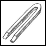
Figure 2 |
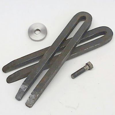
The most important part in machine table furniture is the "U" clamp.
You will find these all over old shops and in sizes from 3/8" (10mm) bar to 1-1/2" (38mm) bar.
Most are made of square stock but ocassionaly they are made of round.
These were made of 1/2" (13mm) hot roll square stock for use on an old 20" drill press.
|
|
|
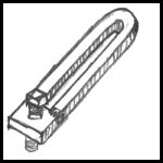
Figure 3 |
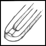
Figure 4 |
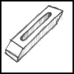
Figure 5 |
|
-GURU
|
|
Some U-clamps have leveling screws on one end like figure 3.
The clamp in figure 4 has a soft brass pad brazed onto it.
Commercial clamps look like figure 5 and have step teeth in one end.
Plain ones like figure 1 are the most common and work as well as the others.
|
|
|
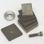
Figure 6 |
With your U-Clamps you will need heavy clamping washers, spacer blocks and bolts of various lengths.
The bolts should be purchased in sets equal to the number of clamps and in a size that fits the T-Slot nuts used on your machine.
I generaly make sets of four.
Bolts in 1" (25mm) increments or less are good to have.
I used high strength bolts but "heavy hex" bolts and nuts are good to use when available.
|
-GURU
|
|
The clamping washers can be made or purchased.
Spacers blocks are cut in sets from available stock.
Mine are from hot roll, cold roll, stainless and brass. Whatever I had around.
|
|
|
|
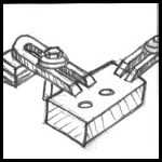
Figure 7 |
Here is a typical clamping arrangement.
|
|
|
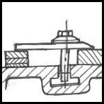
Figure 8 |
Normally the bolt wants to be close to the work and the spacers at the end of the clamp.
Here a T-slot nut is in use.
|
|
|
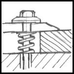
Figure 9 |
When the same clamping setup is to be used over and over it helps to put a spring under the bolt. This raises the clamp when loosened and holds the pieces in place.
|
|
|
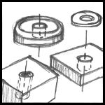
Figure 11 |
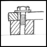
Figure 12 |
|
|
-GURU
|
|
Some of my thicker spacer blocks have tapped holes in them so they can be attached to the U-Clamps.
This also helps keep things together in repeat or production setups.
Commercial spacers have saw tooth notches cut into them so that they can be adjusted in steps as pairs or the clamp bar adjusted in the steps.
These are convienient to use but are dificult to make.
Your clamping washers can be turned, cut from round stock and drilled or made from flat bar.
They can also be purchased.
I like mine to be almost as thick as the bolt diameter or just a little smaller.
It is also necessary to have a handful of standard flat washers with your furniture kit.
|
|
|
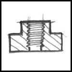
Figure 13 |
T-slot nuts are best purchased rather than made.
Commercial T-slot nuts are not threaded all the way through.
This is to prevent damage to the machine table.
|
|
|
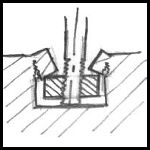
Figure 14 |
IF a bolt extends through the T-nut it pushes up on the T-slot.
If this occurs before the clamp tightens the worker often keeps tightening the bolt until the T-slot breaks in the attempt to tighten the clamp.
Beware of this situation and DO NOT try to force bolts through the unthreaded portion of the T-nut.
|
|
|
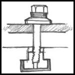
Figure 15 |
Use a stack of plain washers to get the bolt into the tightening range.
Studs can also be used with T-slot nuts and is actually the preferred method.
You can also use heavy head square head bolts in the T-slot.
|
|
|
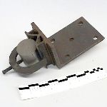
Figure 16 |
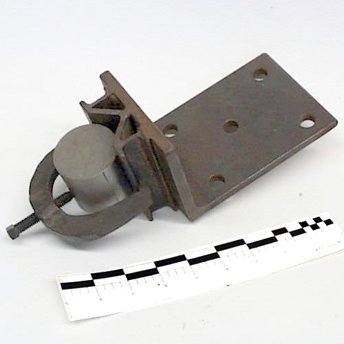
This is a special right angle base V-block I made for a job. I've used the same method to make plain V-blocks. These are not precision blocks but they are fine for most work.
Click image for detail.
|
|
|
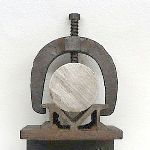
Figure 17 |
The V portion is made of 1-1/2" x 1/4" angle iron and the side slots from 1" channel.
The clamp was forged and fits 2" to 1" diamaeter stock without a spacer.
Click image for detail.
|
|
|
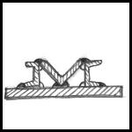
Figure 18 |
The angle iron was first welded to the plate and adjusted until it was equally aligned right to left. Then the channels were added. There are short welds inside the ends of the enclosed triangular areas.
When the welding was completed, some more "adjusting" was done with a hammer and then the welds at the top ground flat.
|
|
|
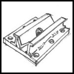
Figure 19 |
For drill press work I drilled a large hole through the center of the block to allow drills to break through into the clear and chips to fall through.
|
|
|
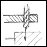
Figure 20 |
To hold and start drills accurately a "drill jig" or a "drill jig bushing" is used. For common work this can be a simple piece of mild steel with an on-size hole drilled through it.
|
|
|
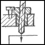
Figure 21 |
For precision or high production work hardened drill bushings are used. These press or slip into a reamed hole and are held in by a small screw if not a pressed in busing. These are inexpensive, long wearing and very precision. Repeat holes located to within .002" are easily achieved from relatively primitive tooling. If you need to make interchangable parts OR parts that accurately fit other parts this is the way to go. Often drill jigs are made on a precision milling setup but then can be used on simple drill presses to produce precision parts.
|
|
|
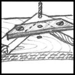
Figure 22 |
This is a crude fixture I made to drill wooden book covers. The jig is made of wood with a steel bar locating the drill. Hundreds of holes were drilled with this fixture over a period of years without it showing any wear. This same fixture or something like it could be used for light drilling operations in steel parts like hinges that all needed to be the same. This also avoids doing repetitive layouts.
|
|
-GURU
|
|
This was part one of a multi part series on drill press tooling.
The next part will cover more sophisticated clamping, taping and boring on a drill press.
|
|
-GURU
|
|
Questions, comments?
|
|
PF
|
|
Splendid Jock. . . being self taught , this is a real help. . . thank you!
|
|
jerry
|
|
Thanks again Jock, especially for the jig for round.
|
|
|
|
I love the v-block thing..
|
SCOTT
|
|
The open end models will spread if you apply too much presure.
I like the closed ones better.
I also use one with a round bar welded on one end.
This works great when holding in a hole on the end of your work.
A piece of copper tube around this round end will help keep from damaging a threaded hole.
|
|
-GURU
|
|
Yes, that is also a common style that I forgot about.
These provide a three point support that assures tangent clamping of the work and work well on uneven surfaces.
The copper tubing on the round end is a good idea. Here is an added drawing.
|
|
|
|
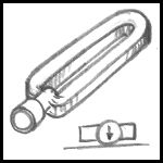
Figure 23 |
|
|