|
Hugh McDonald
Your Own Personal Steel Rolling Mill How to Build and Operate it.
CD-ROM, Adobe Acrobat PDF,
|
|
Review - by Jock Dempsey and Wayne Parris Original detailed review
The McDonald Mill is not just a set of plans but a FANTASTIC invention!
It is NOT just another rolling mill.
This is a revolutionary NEW machine that in any other era would have been patented and made the inventor huge profits.
Hugh McDonald has done what thousands of smiths (including myself) have dreamed of and schemed over and never came up with the solution.
In these notes are examples of work Hugh does with the mill plus some in depth discussion on the Roller Mill's controls and why it has three separate systems that may seem, at first sight, to do much the same thing; regulate the distance between the rollers. If you are comfortable with the CD-ROM format and have a good printer to print out the drawings then the CD is a better resource than the print plans. 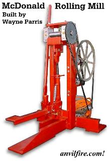
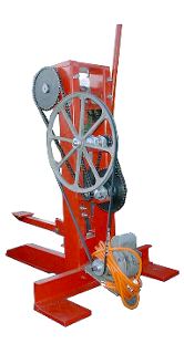
A Builder's Experience by Wayne Parris In the photos above my machine was less than 24 hours old. I had just finished it and was on my way to a blacksmithing event in Southern California. The machine was untested until the event. At the event, I had a LOT of interest in how it worked and how hard it was to build. It was not hard to build at all. (Click images for enlargements) The motor that was fitted first was a tired old 1/2 HP 1725 RPM motor I had on hand. At the event, I soon discovered that I could take a bigger bite on the stock than the motor could handle. This required a little slower going than it would have normally taken. This motor was replaced after the show with a 1 1/2 HP motor and there have been no further motor problems. I have a solid back ground in reading blue prints and the construction of tools as I have been a tool / jig and fixture maker and tooling inspector for Boeing for 24 years now. I have my own machines, mill, lathe etc. I found the overall quality of the drawings quite good and detailed where they needed to be. The hardest thing I had to deal with was the conversion of the metric sizes to U.S. inches. After a while though, I learned what metric size was what with U.S. stock. I found that the conversion of sizes was not an exact 1 for 1 so I went to the next larger stock size over what the plans called for. This required the slight adjustment of dims where 2 or more parts came together and the different stock thickness would have caused interference. This was not a big problem though. I went stronger than the plans because that is what I had on hand. I used rectangular tubing over U channel due to availability, any deviation I made from stock call out was either a thicker material or a stronger shape, again only due to what was on hand. Because I had access to a milling machine, I milled the mating surfaces of the vertical posts and the sides of the movable jaw to make a good fit. I also milled the mounting surface of the bearing block for the upper roller to be 90° to the surface I milled to make a good fit for the lower jaw. This then gave me good surfaces to clamp holding structure to while welding the unit together (the plans call for a bolt together construction). Only .003" of a shim was required to get the upper roller to turn free after welding. Machining these surfaces is not necessary but it made final adjustments easier. I used bronze bearings throughout as they were inexpensive and there was a local source for them. My first reduction of RPM brought the shaft speed down from the motor to a safe speed for the bronze bearings on the first counter shaft. Self aligning bearing blocks were used for the speed reduction shafts to reduce any alignment problems. The size of the first pulley was again chosen by what was the largest pulley I had in my junk pile. I bought the # 40 chain, and sprockets from McMaster-Carr. The final speed of the upper roller is 22 RPM with a 2-1/8" OD. The bearings for the upper roller are 2" diameter x 2" wide. This traps the upper roller between them and keeps it in place. I cut keyways on every shaft that is driven to keep the pulleys/sprockets from slipping. I have about 40 hours of construction time in the project. You will need access to at least a lathe for this project as you are required to make a cam. This was easy to do following the plans and I would think that a machine shop could make you one at a reasonable cost. Also, you should make guards to keep fingers etc. out of the belts and chains. How well does it work? It is an easy, QUIET, vibration free machine to use. I have not tried to weld with it yet but it is on the schedule to be tried. I use it mainly for drawing stock. I am able to turn two 10" long 7/8" diameter bars of SAE 4130 into a set of 24" long tongs, complete except for the rivet in under an hour using a gas forge. The first bite or time the stock goes through the machine is the hardest to judge. If you take too large of a bite, you fuller the stock and the machine can't then pull it through. The notch adjustments are setup perfect and after you have the stock through the first time, the notch steps have the stock flowing smoothly through the machine. I have found that if you do take too big of a bite and fuller the stock, stop right there, re-heat the stock and put it in the machine UPSIDE DOWN the next time through. This will allow the fullered section to flow through the machine, if you do not do this it is much harder to get the fullered section to smooth out. I have plans to someday add interchangeable rollers for the bottom roller. The bottom roller is quick to change and would be an easy way to get texture or half rounds or half hex or any other shape you could put onto a roller. Though I do not use the machine daily, it was worth the effort it took to construct. Like any tool, if you have it, you will find a way to use it. If it is not there, you find another way to do the work. This would be a great tool for someone who lives in the city as it is so quiet. For the processes it does, it does them well. It will not replace a power hammer but it will save you lots of sore arms when drawing! 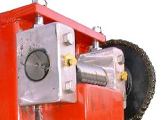 Another change Wayne made was to replace the solid brass bearing blocks with aluminium blocks and standard sintered bronze bushings.
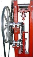
This is an example of doing with what you have. In many situations where large stock is not available casting the bearing blocks is the best option. However, large blocks of mild steel or aluminium with bushings or 660 brass bearing stock is also an option. Using commercial ball bearing pillow blocks is yet another option. |
|
Sold in the anvilfire.com store!
Hugh McDonald
Price: 25.00$ US plus0 S&H | ||
|
