DESIGN is art, it is compromise, it is decision.
You start with an idea, fit parts and materials and hope it all works according to plan.
While most of our plan worked we also learned from experience.
None of the parts below will be made this same way again.
Changes from the original for the X2:
- Taller guides
- Middle hole removed from spring
- Drive wheel on back
-
Turnbuckle type height adjustment.
Acme bolt into hollow tube "nut".
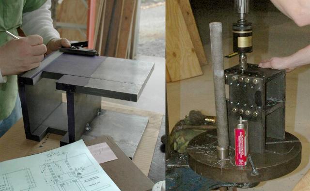
Above left, laying out the guide box assembly.
The guide box was built from standard sections of 3/4" cold finished steel to avoid machining the edges to square up the stock.
It may be more economical to use flame cut side plates and the 3/4" CF bar for the middle sections only.
Most of the holes were taped by hand as they were drilled but the many adjustment screw holes were power taped with a Tapmatic Tapping head.
The X2 design will use taller guides, 10.5" or taller rather than 8".
The longer the guides the more stable the ram for a given amount of play.
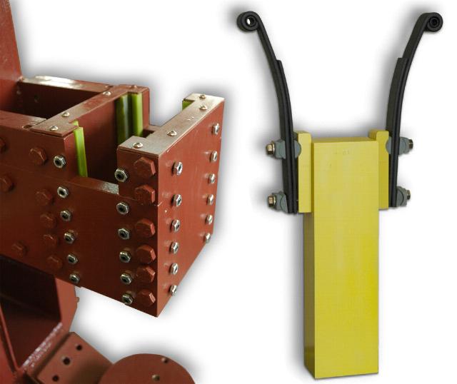
The finished guide box and ram.
Both were made out of (relatively) precision cold finished steel.
The ram was made from the largest CF (cold finished) steel we could find at the time, 3.5" x 5".
A length was 36". We sawed it in two and had a piece left over for the pitman heads.
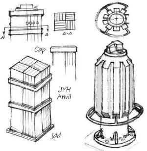 OUR Anvils used designs we published on anvilfire's Junk Yard Hammer page.
The square anvil used all new steel. 1" x 5" HR bar was used to build up a 10" square anvil onto which we attached a 9" diameter cap.
The round ribbed anvil was made from some 6-7/8" round I had gathered years ago for hammer anvils.
The added 2 x 2's were purchased new.
We did not chamfer the corners of the round anvil as shown.
Instead we drilled and taped holes outside the die space for bolting on attachments and larger bottom dies.
Our crank plate was made from cookies sliced off the 6-7/8" round anvil stock we had on hand.
Otherwise it would need to be flame cut plate.
After welding to the shaft it was slightly crooked so we had to machine it.
Facing the the surfaces square to the shaft was the only turning job that could not be done on our little 6" lathe.
The counterweight was welded on after the machining.
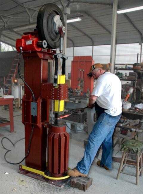
The Drive Wheel
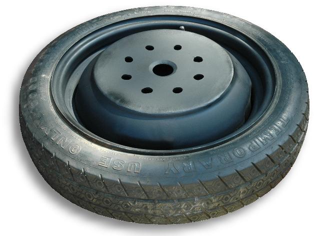
What seemed like a simple idea ran awry when it was determined that the center or a standard wheel would not let us bolt the wheel to back of our flange.
So we cut the center out of the wheel and welded in a 10" diameter 1/4" thick plate.
This was then drilled for the shaft and bolt holes.
A second issue arose when talking to folks who had run their tire hammers hard.
The tires would wear in one spot and need replacing.
However, compact spares are difficult to change and most tire shops cannot change them.
A new replacement tire costs double (about $300) that of a standard tire.
Besides these issues the common Tire Hammer modifies the wheel such that the tire cannot be changed on any normal tire changing equipment.
To get more wear out of the tire we decided to double the bolt holes from 4 to 8.
However, this change was made after the others had been completed and the layout bolt circle lost.
The new holes did not quite line up thus the "egging" seen above.
Future designs will put the tire on the back of the hammer and use an unmodified wheel/tire assembly.
Standard wheels and tires will be considered as well.
While some folks have no trouble finding compact spares we had a difficult time finding two alike and the pickings in some large wreaking yards were few due to the high demand.
Scrap compact spares are in high demand due to the high replacement cost of the "temporary" tire.
Personally I prefer to replace them with a full size wheel and tire so that if I have a flat I do not have to go directly to the tire store. . .


Changes from the original for the X2:
Turnbuckletype height adjustment.Acme bolt into hollow tube "nut".
Above left, laying out the guide box assembly. The guide box was built from standard sections of 3/4" cold finished steel to avoid machining the edges to square up the stock. It may be more economical to use flame cut side plates and the 3/4" CF bar for the middle sections only. Most of the holes were taped by hand as they were drilled but the many adjustment screw holes were power taped with a Tapmatic Tapping head.
The X2 design will use taller guides, 10.5" or taller rather than 8". The longer the guides the more stable the ram for a given amount of play.
The finished guide box and ram. Both were made out of (relatively) precision cold finished steel. The ram was made from the largest CF (cold finished) steel we could find at the time, 3.5" x 5". A length was 36". We sawed it in two and had a piece left over for the pitman heads.
The square anvil used all new steel. 1" x 5" HR bar was used to build up a 10" square anvil onto which we attached a 9" diameter cap. The round ribbed anvil was made from some 6-7/8" round I had gathered years ago for hammer anvils. The added 2 x 2's were purchased new.
We did not chamfer the corners of the round anvil as shown. Instead we drilled and taped holes outside the die space for bolting on attachments and larger bottom dies.
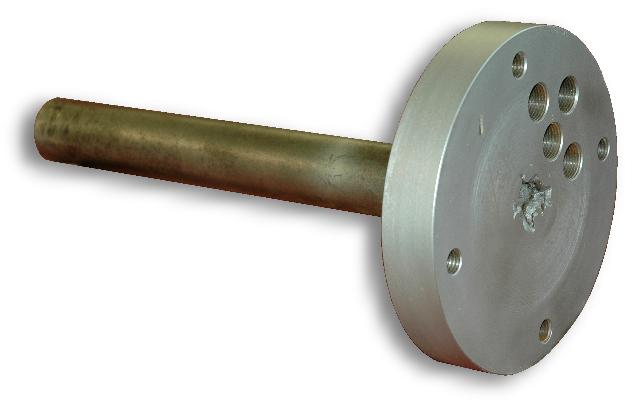
Our crank plate was made from cookies sliced off the 6-7/8" round anvil stock we had on hand. Otherwise it would need to be flame cut plate. After welding to the shaft it was slightly crooked so we had to machine it. Facing the the surfaces square to the shaft was the only turning job that could not be done on our little 6" lathe. The counterweight was welded on after the machining.
The Drive Wheel
What seemed like a simple idea ran awry when it was determined that the center or a standard wheel would not let us bolt the wheel to back of our flange. So we cut the center out of the wheel and welded in a 10" diameter 1/4" thick plate. This was then drilled for the shaft and bolt holes.
A second issue arose when talking to folks who had run their tire hammers hard. The tires would wear in one spot and need replacing. However, compact spares are difficult to change and most tire shops cannot change them. A new replacement tire costs double (about $300) that of a standard tire. Besides these issues the common Tire Hammer modifies the wheel such that the tire cannot be changed on any normal tire changing equipment.
To get more wear out of the tire we decided to double the bolt holes from 4 to 8. However, this change was made after the others had been completed and the layout bolt circle lost. The new holes did not quite line up thus the "egging" seen above.
Future designs will put the tire on the back of the hammer and use an unmodified wheel/tire assembly. Standard wheels and tires will be considered as well. While some folks have no trouble finding compact spares we had a difficult time finding two alike and the pickings in some large wreaking yards were few due to the high demand. Scrap compact spares are in high demand due to the high replacement cost of the "temporary" tire. Personally I prefer to replace them with a full size wheel and tire so that if I have a flat I do not have to go directly to the tire store. . .